UML Design Class Relations
During the execution of a program objects collaborate in different ways. This collaboration is most often different kinds of messages sent between objects, e.g. method calls. To be able to send a message from one object to another there needs to be a link between the objects, i.e. the sending object needs to know about the recieving object in some way. This link can be formed in two basic ways, ether the sending object contains an attribute that holds the recieving object, or the recieving object is known as an argument or local variable. A local variable object can either be created, or recieved as a return value.
In a class diagram we show all the possible links an object of a class can have, in the form of associations and depdenencies. In addition we can show if a class inherits another class, or if it implements an interface.
This gives us four basic relations between classes in UML: dependency, association, generalisation and realisation. The dependency is the most generic of the four and if none of the others apply a dependency is often used.
Using the relations in a class diagram we can reason about properties such as reusability, order of implementation, complexity, maintainability. For example, a class with many outgoing relations can be considered fragile and complicated, it is aware of many other classes and could thus be impacted by change in any of these. Reusing such a class is often hard as you would need to either remove many relations, or bring along many other classes when reusing. On the other hand a class with many incoming relations can be hard to change without breaking the whole system e.g. it is a hot-spot that could benefit from further division.
In practical diagramming showing all relations in a full class diagram often creates a very messy diagram. While a mess can be a good visual cue for refactoring ("this part looks too messy") it is common to not show every single relation, especially dependencies. Good tooling is essential and can provide different perspectives and levels of detail.
Design Class Diagram Notation Crash Course
Association
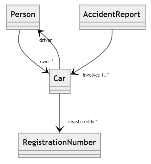
An association is a persistens relation that can exist between two or more objects. That the relation is persistent means that it exists for some period of time, typically it persists between multiple method calls. As such the associations define the major structural relations. In design level class diagrams the association has navigability (direction), multiplicity and a role name, the association name is not used.
In practice the multiplicity 0..1 are often not shown explicitly in a diagram. E.g a car can be without a driver, but never without a registration number.
UML
In source code an association is often implemented using an attribute, we do not typically show this attribute in the class diagram as it would be redundant.

Java
As associations are persistent they must be implemented using fields in Java. The association role name corresponds to the implementing field name. In practice the only multiplicities we can enforce syntactically are 0..1 and 0..* E.g. having a field that can contain 0 or 1 object, or a field that can contain 0 or many objects. Other mutliplicites needs to be enforced by writing code for example by adding appropriate constructors.
It may also be the case that for practial reasons you allow the 0..* multiplicity in the code while the design specifies another multiplicity. I.e. you first create an empty object and then add some other objects to is via special methods.
Typically the design does not dictate how multiplcity * should be implemented.
Dependency
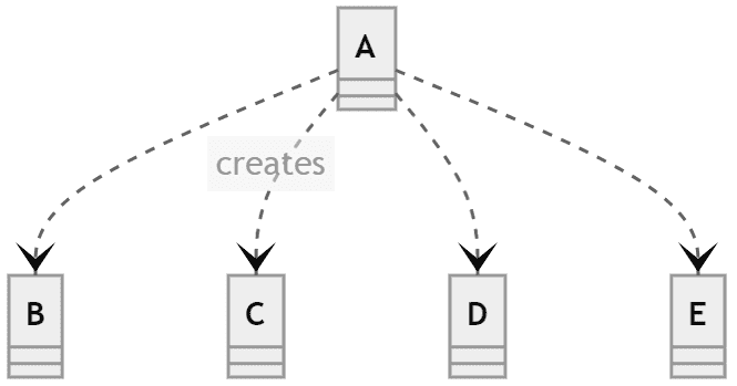
In a design class diagram the dependency relation means that one class needs another class to be able to work (e.g. A cannot be compiled without B). If we need a relation but we cannot refine it to some other more specific relation (association, realization or generalization) dependency should be used. Additional dependencies are typcially not added if we already have some other relation. Typically we also do not show dependencies from a class if the dependency is already in a more general class or an interface.
In general we can find the dependency relation in many different diagrams, and also it is often used in general software discussions.
In some cases the dependency has a stereotype that explains what the dependency is caused by. For example creates that indicats that objects are created.
Java
In Java dependenices are formed by having local variables, arguments in methods, return types or calling static methods.
Realisation and Generalisation
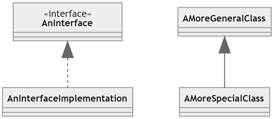
Realisation describes the fulfillment of e.g. an interface. Generalisation describes that e.g. a class is part of a generalisation/specialisation hierarchy. For realization the lollipop notation is also available, but it is often more common in component diagrams.
Java
In Java generalisation is implemented using inheritance i.e. extends, and realisation is implemented using implements.
Composition and Aggregation
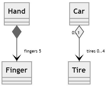
Composition and aggregation are special types of assocaiations. Composition indicates a strong whole part relationship where the part cannot be removed from the whole. I.e. the part lives and dies with the whole. For example a hand is composed of a palm and five fingers. In some cases also the parts cannot be shared with other objects, e.g. a finger cannot belong to two hands.
Aggregation indicates a loose whole part relationship where the parts can live without being part of a whole, in some cases the parts can also be shared by multiple whole objects at the same time. We can think of for example a car that has four tires, the tires can be removed from the car and put on another car, however they cannot be part of two different cars at the same time.
The exact interpretation of composition and aggregation is debated for design class diagrams, esp. their interpretation and implementation in garbage collected languages. Typically composition can be useful in multithreaded applications where sharing objects can be problematic, also composition can be used to indicate how objects should be copied. E.g. if a hand object is to be copied, the copy cannot share the finger objects between them. Howeve, this interpretaion of composition and aggregation is not considered standard among developers.
When interpreting a diagram what contains composition and/or aggregation the standard interpretation is to consider them to be associations. Exactly, what is meant by the composition/aggregation must be made clear on a case to case basis.
Ther rule of thumb is to not spend too much time on debating compositon v.s. aggregation but rather use association, esp. if the design is to be implemented in a single threaded garbage collected language.
Java
Syntactically composition and aggregation are implemented as associations, i.e. using fields. There is no easy way to know if composition or aggregation is actually used by just inspecting Java code and it is more or less up to interpretation. Hence for Java code composition and aggregation are not that useful. Do not spend time on these concepts, just use the plain asociation.
If aggregated values are not be shared the implementation is often rather tricky. This is just an example on how this could be achieved, but definitely not the only way.


