During the course you are expected to hand in the following assignment. You should also be prepared to discuss your solutions oral.
Implementations can be done in any programming language but I suggest Java, C# or JavaScript as good candidates.
More details will follow shortly.
Task1
Implementation of a line drawing program. The plotting of the line between two specified endpoints should not use built in line drawing functions but rather implement your own method. The only built in method you are supposed to use is a pixel plotting function. Ironically in some implementations you will have to use a line drawing function but with the same start and end coordinates when plotting individual pixels.
The choice of start and end positions can be assigned by keyboard or preferable by mouse input. For testing purposes I suggest using hard coded numbers.
For a higher grade (VG) you can choose to implement the rendering of other primitives like a circle, anti aliasing or the drawing of thicker lines.
Testing of your implementation:
To verify your implementation you can try to first draw the line with your code in one color and then use the built in draw line with another color. If your implementation differs it will be visible as pixels with different colors. To check for all errors you also need to do it in the opposite order.
Task2
Task two is an enhancement of task one. So you can reuse your code from the first one and have them examined together as a package.
List of techniques used in the task:
- Transformations, Rotation, Scaling
- Clipping and Culling
- World View to Screen View port Transformations
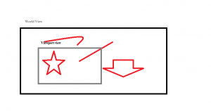
In this task you will create a world view (see image above) where you have some objects. The best way is to create the objects with lines for which you already have a rendering function.
Store the lines in some sort of list so you can access them easily.
The rendering of the objects happens into your View port which is smaller than the world view and movable. To achieve this your lines will have to be translated and clipped against the view port. Primitives falling totally outside the view port can be culled instead of clipped. The view should be movable during runtime.
If you are aiming just for translation it can be implemented easily with just some simple math in your code.
If you want a higher grading on the course you can optionally implement scaling and rotation for your view port. In that case it’s a better option to use matrices for the math so you can combine everything into one place. You can also implement clipping of more advanced primitives than lines.
Testing of your implementation:
Verify that you can move your view so only a small part of your world is visible at any time.
Verify that your lines are clipped with your code so you doesn’t use the built in clipping functionality in java. Create your clipping size smaller than your actual drawing area to verify.
See links under lecture 2 for references to reading materials.
Task3
In this exercise we are moving from 2D drawing to hardware accelerated 3D drawing with OpenGL.
Draw a 3D Cube in a View port. Calculate and specify your vertex coordinates manually.
It’s not allowed to use glBegin/glEnd for drawing primitives. Indexed drawing or using VBO is preferred but not mandated.
Make use of OpenGL:s matrix modes to move, rotate and scale your cube.
If you are using Java for the exercises you will have access to OpenGL 2.0 where shaders aren’t needed.
Jogl setup tutorial.
If you are using WebGL for your your implementation you also need some shaders for it to work. A bit more work in this early stage. A tutorial can be found here:
WebGL tutorial for simple shaders and rendering of a triangle.
Task4
In this task we will apply textures to our models. Create a plane consisting of 2 triangles. For each vertex you want to specify texture coordinates instead of color values. Texture coordinates are specified with the function glTexCoordPointer and you will also need to enable glEnableClientState(GL2.GL_TEXTURE_COORD_ARRAY);
Now load a texture and make sure it shows up on the plane in the right way.
Create code so you can show your textured plane in the following ways. Using a chess pattern or black text on white background as your image can sometimes visualize the results better.

- View the plane from the front covering as much of your drawing area as possible.
- Move the camera/plane away from each other. What happens when the plane gets small?
- Rotate the plane so it has an angle above 90 degrees to the camera and looks like a floor in a corridor. How does the texturing look now in different parts of the screen?
- Try the above with mipmapping turned on and off. Can you see a difference?
http://gregs-blog.com/2008/01/17/opengl-texture-filter-parameters-explained/
http://download.java.net/media/jogl/jogl-2.x-docs/com/sun/opengl/util/texture/awt/AWTTextureIO.html
Task5
In this assignment we will work a bit more with how things are drawn on screen.
The function glViewport can be used to specify which area of our screen that should be drawn to at a given moment.
http://www.opengl.org/sdk/docs/man/xhtml/glViewport.xml
This can be used to draw the same model from different perspectives like in this example.
In your application that draws a cube, modify the drawing code to render the cube from two or more different directions into there own view ports. Each view port should have the camera placed in different positions and/or the model should be of different orientation or size. To save the current matrix state use PushMatrix and PopMatrix for that.
Other useful functions are:
- glMatrixMode
- glLoadIdentity
- glClear
- gluPerspective (In jogl you need to create GLU glu = new GLU(); because this function is a utility function.)
- glTranslate
- glScale
- glRotate
- glPushMatrix
- glPopMatrix
gl.glEnable(GL2.GL_CULL_FACE);
gl.glCullFace(GL2.GL_BACK); //Options: GL_BACK, GL_FRONT, GL_FRONT_AND_BACK
gl.glFrontFace(GL2.GL_CCW); //Options: GL_CCW, GL_CW
Use the different options for each function and observe what happens.
Disable culling by commenting out your code above or use the function gl.glDisable(GL2.GL_CULL_FACE);
Now implement your own back face culling for one triangle.
It can be done in two ways.
- Calculate the normal for your triangle and for your cameras view direction. The normal for a triangle can be found by taking the cross product of two vectors between the vertices. Then take the dot product between these vectors and you will get a value telling you if they point in the same or opposite directions. Values greater than or equal to zero can be culled.
- Calculate the winding order of the triangles vertices. http://mathforum.org/library/drmath/view/55343.html
Task6
This 6th task is voluntary and can be done to increase your grade of the course.
So far we have used mouse/keyboard input or code to specify lines and more advanced models. This is not very practical in bigger solutions when we to start with need some tools to generate the models. For this purpose we can instead use a model file format that saves the information needed for drawing a model. There exists countless of formats but one that most tools can export to is .obj format. You can find tree such files in this packed zip file.
Your task is to create a loading method that can parse the information in at least the cube.obj file and render it with a texture applied to it if texture coordinates exists. Remember the following important information:
- Only parse the file once during loading and store the information into arrays or VBO for rendering.
- Data is stored in different lists for vertex (v), normal (vn) and texture coordinates (vt). This data is den referenced from the faces list (f) that contains all faces of the model. The references in the faces list points to the v/vn/vt lists so you will have to rebuild the full data.
For example the cube only has 4 texture coordinates saved while 8 vertex positions can be found in the file. The texture coordinates are then reused from several faces. - Depending on the number of parameters for each face they are stored as Triangles (3) or Quads(4). That means you will have to change the drawing between GL_TRIANGLES and GL_QUADS
Don’t hesitate to ask questions if you need help with your implementation or debugging.

